Tuesday, September 11, 2012

End Mill Performance & Spindle Torque


Many times when machinists look at cutting tool speeds and feeds, they are often misled into believing that they should be concerned with horsepower. The real driving force is not horsepower, it’s TORQUE. In order to maximize your speeds and feeds you should have a good understanding of how your CNC machine develops and holds torque.

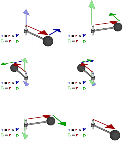
Torque is the measure of how much immediate rotational force a spindle drive motor can generate. The image at the right shows Relationship between force F, torque τ,linear momentum p, and angular momentumL in a system which has rotation constrained in one plane only (forces and moments due to gravity and friction are not considered).

End Mills in the Old School
Traditionally, a 1” diameter end mill would require high torque and low speed , while a 1/4” diameter end mill would require high speed and low torque. Generally speaking, different end mill diameters & geometries have different requirements for both Horsepower and Torque. 

Destiny End Mills
However, as a general rule most of our end mills are designed to be run at high RPM regardless of diameter. We prefer high speed AND high torque. Our tool geometry is optimized for high speed machining. 

A while back we talked about our tooling geometry and how our end mills can have up to 3 rake face in the cutting edge of the tool. As the tool enters the cut and takes the first 3-5 revolutions (and remember you can be running up to 18,000 Revolutions Per Minute) there is a tremendous amount of cutting force placed upon the tool and you can notice your HP meter jump as the tool enters the cut multiple times. This entry is when the torque curve on your CNC machine is the most important.  Older CNC machines where designed to quickly reach peak torque between 1200 - 3000 RPM and then drop off. Newer, high speed machining centers hold constant torque.

Think of it like this. When a hydrofoil starts off from the dock it's not up to speed so it requires both HP and torque until the hull of the boat lifts off the surface. At that point a couple important changes happen in power consumption because the ship has "lifted" from the surface: The coefficient of friction has dropped dramatically. Similarly, once our tools are "in the cut" the chip formation "lifts" from contact with the gullet of the tool (the 'core diameter"). Horsepower is not quite as important as maintaining torque in the cut especially as you interpolate around a corner in a full slotting application.

We like Constant Torque
Spindle Torque Efficiency
Because of the unique geometry, our tools perform best under constant torque.  Take a look at the torque curve for your CNC machine. If you have a 10,000 RPM spindle motor and the torque drops from it’s constant peak at 8200 RPM then 8200 RPM would be your maximum RPM. Take this into consideration FIRST when calculating the specific speeds and feeds.

Saturday, September 8, 2012

The Diamond Back Rougher


Our Diamond Back Rougher is designed for maximum Metal Removal Rates (MRR) in Non Ferrous Applications. Although the chart below depict a maximum chip load per tooth (IPT) value, your maximum may be lower due to Machine Horsepower, Machine Torque, Toolholder and/or workholding. 

The “General Operating Range” is based upon 2X diameter (ADC / DOC)  in full diameter (RDC / WOC) SLOTTING.   The minimum Chip Loads remain constant for all applications, however, the maximum chip loads can vary for side milling applications in Finishing, Heavy Roughing  & Light roughing.

Diamond Back Rougher Chip Load range for Non Ferrous "N" type materials

Tuesday, September 4, 2012

Our Philosophy on End Mills: Coatings


We've spent a great deal of time insuring that our coatings work in conjunction with all the other aspects of our end mills.  We have three primary coatings for our tools. Here's some details on what they are and where to apply them for your cutting material applications.

Black Stealth
Black Stealth Coating MoS2

Molybdenum Disulfide (MoS2). The easiest way to understand our Stealth coating is to think of the coating as being ‘clear’ and not ‘black.’ As soon as the tool enters the cut many people comment that the “color has worn off.”  We can assure you that this is not the case. There’s several physical and chemical changes that cause this visual change and space does not permit here to explain the science. That’s part of the reason we call it “stealth” because you can’t see it any more!  What’s important is the this coating has a lower co-efficient of friction than just about everything else on the market. Our geometry works ideally with this coating. Used for our Viper and DiamondBack series tools which are for all Non Ferrous Alloy milling (N)

AlTiN 
AlTiN Coating

Aluminium Titanium Nitride  This PVD coating has a gradually increasing percentage of aluminum added as it goes through the coating process. It gradually increases in the amount of Aluminum from the substrate interface until it reaches the outer surface of the coating, where there is a higher percentage (up to 65%) of aluminum in the film. As the tool heats up, the aluminum converts to aluminum oxide, staying in the film. This coating provides exceptional oxidation resistance and extreme hardness. AlTiN retains its hardness when the temperature is 800° to 930° C (1,470° to 1,700° F) This coating is ideal for dry machining environments. Used exclusively on our Raptor products for all P - Steels (blue), M - Stainless Steel (yellow), K - Cast Iron (red), and S - Hi-Temp Alloys Special Alloys & Titanium - (brown) materials. 

Please keep in mind that this coating CANNOT be used in Aluminum (N) machining because the Aluminum in it would have an affinity to itself and cause workpiece adhesion to the cutting tool.

X-Treme 
TiAlN Xtreme Coating

Titanium Aluminium Nitride (TiAlN) This monolayer PVD coating has high hardness and excellent thermal stability that protects against premature tool wear. It also has excellent oxidation resistance allows high speed and semi dry or dry machining operations. Used for our Cobra and Python series tools which are for all P - Steels (blue), M - Stainless Steel (yellow), K - Cast Iron (red), and S - Hi-Temp Alloys Special Alloys & Titanium - (brown) materials


Saturday, September 1, 2012

Our Philosophy on End Mills: Tolerance


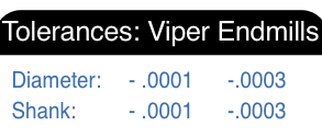
When we talk about tolerance we are actually referring to two components of our end mills.  Our shank diameters are held tighter than standard h6 industry specifications of -0.0001” / -0.0003”.  Our Viper and DiamondBack End Mills are held to -0.0001" / 0.0003" on diameter and shank. However, that is just part of the story...

We’ve really concentrated a lot of time on the grinding tolerance as well. When you look at our competitors under a microscope many times you will see that the primary and secondary grind finish looks like a washboard texture because of the wheel that was used to finish grind it with.  

End Mill performance in high speed machining is dependent upon the surface roughness (topography) of the rake face and and relief face of the end mill.  Better, smoother ground surfaces reduce the co-efficient of friction and permit the tool to perform better “in the cut”.  As we talked about in our previous posting with regard to geometry, we make every attempt to reduce the co-efficient of friction that a chip encounters as it is being formed into 6's & 9's in our end mills.  We take special care to insure that our wheels are re-dressed quite often to maintain consistent surface finish. And that has an impact on coating adhesion as well. We'll be discussing that in our next posting.